Software Rasterizer: Drawing a Triangle
The world of 2D graphics is built on triangles as the main primitives for drawing. In fact, even lines and complex polygons are often broken down into triangles. This greatly simplifies the rendering process and is fundamental to how computers draw shapes efficiently.
Table of Contents
I won’t go into what a triangle is exactly—it is simply a polygon with three points called vertices.
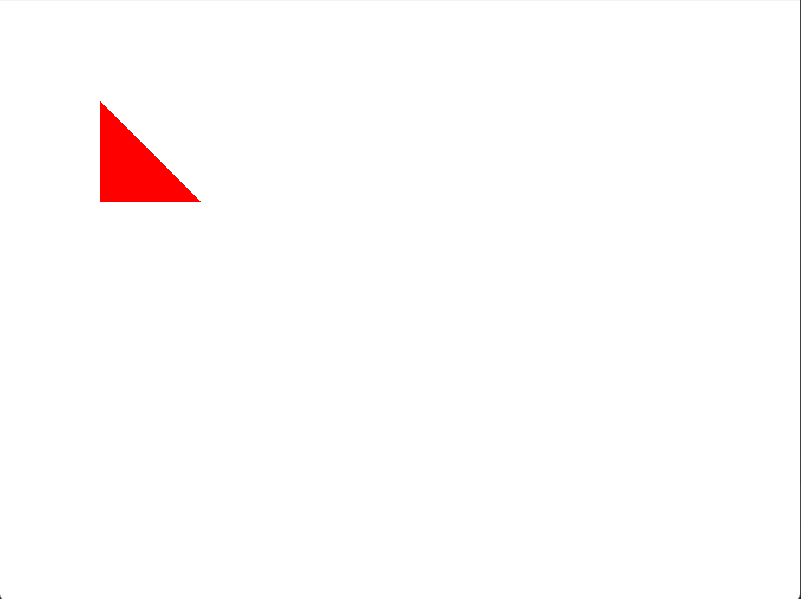
Something like this:
How Vertices Are Named
When working with triangles, each vertex usually gets a name such as A, B, and C. This makes it easy to refer to them when performing the math to fill the triangle’s area with pixels.
For example, in a triangle defined on a 2D screen:
Vertex A = (100, 100)
Vertex B = (150, 200)
Vertex C = (200, 100)
Naming vertices consistently helps define the triangle’s winding order, which is critical for a rasterizer to know how to fill it correctly.
Triangle Winding Order
In 2D graphics, we do not worry about which way a triangle is facing a camera. Instead, the order in which vertices are defined matters. This is called winding order or orientation.
The order can be either clockwise or counter-clockwise:
- Clockwise (CW): The vertices are defined in a clockwise direction like the hands on a clock (A → B → C).
- Counter-Clockwise (CCW): The vertices are defined in a counter-clockwise direction (A → C → B).
This matters because our software renderer needs a consistent rule to determine which
pixels are inside the triangle. Most rasterization algorithms rely on the winding order to figure out the triangle's edges and fill the space between them.
Here is a visual example:
By establishing a consistent winding order, such as counter-clockwise, we can write a much simpler and more efficient filling algorithm. This is a fundamental concept that makes software rasterization fast and reliable.
This tutorial uses the counter-clockwise (CCW) convention because it is widely used.
Filling Our Triangle
To understand how the GPU fills triangles, we will implement the logic ourselves. This approach is slower but makes the learning process much clearer.
We need a method to determine whether a pixel lies inside a triangle. To do this, we use the concept of an edge. An edge is simply a line between two vertices of the triangle.
Consider an edge from vertex A to vertex C in our CCW triangle. The triangle itself always lies on one side of the edge. We can check which side a point is on using the edge function. The edge function is closely related to the concept of a signed distance function.
The Edge Function Explained
The edge function tells us whether a point P(x, y) is on the left, right, or exactly on an edge. For an edge from starting vertex V₁(x₁, y₁) to ending vertex V₂(x₂, y₂), it is defined as:
$$E(P) = (x - x₁)(y₂ - y₁) - (y - y₁)(x₂ - x₁)$$
The result is essentially a signed area of the parallelogram formed by the vectors from V₁ to V₂ and from V₁ to P. The sign tells us the side:
- If E(P) > 0, point P is on the left side of the edge.
- If E(P) < 0, point P is on the right side of the edge.
- If E(P) = 0, point P is exactly on the line.
For a counter-clockwise triangle, a pixel is inside if the edge function is positive or zero for all three edges. Notice that this is equivalent to checking the sign of a signed distance function for each edge. The edge function gives a value proportional to how far a point is from the edge, with the sign indicating inside or outside.
Barycentric Coordinates
We can go further and compute weights that describe how much each vertex influences a point P inside the triangle. These are called barycentric coordinates.
Take a point P inside triangle ABC. Connect P to all three vertices, forming three smaller triangles: PAB, PBC, and PCA. Each sub-triangle's area relative to the main triangle gives the barycentric coordinate of the vertex opposite that sub-triangle:
- Weight for A = area of triangle $PBC$ divided by total area of $ABC$
- Weight for B = area of triangle $PCA$ divided by total area of $ABC$
- Weight for C = area of triangle $PAB$ divided by total area of $ABC$
$$
\begin{aligned}
w_A &= \frac{\text{Area of } \triangle PBC}{\text{Area of } \triangle ABC}, \\
w_B &= \frac{\text{Area of } \triangle PCA}{\text{Area of } \triangle ABC}, \\
w_C &= \frac{\text{Area of } \triangle PAB}{\text{Area of } \triangle ABC}.
\end{aligned}
$$
These weights always sum to one and smoothly interpolate properties across the triangle. The larger the weight for a vertex, the closer the point is to that vertex and the more influence it has.
For even a better optimizations we can do:
$$
w_C = 1.0 - (w_A + w_B)
$$
Here is a visual example with interactive sliders to move the point around and see the barycentric coordinates update:
By moving the point, you can see how barycentric coordinates reflect its distance from each vertex. This is the principle that allows computers to fill triangles efficiently and interpolate colors, textures, or other vertex attributes across a surface. The edge function gives the sign and distance from the edge, while barycentric coordinates provide smooth weights across the triangle, linking geometry directly to rasterization and signed distance calculations.
Implementation
Let's start by creating a simple struct called Point which contains x and y. And let's take this even further. Let's implement it with some basic operations +, *,-,/
in Includes, create a file called Point.h:
#pragma once

struct Point {
    float x, y;

    // Constructor
    Point(float x_ = 0.0f, float y_ = 0.0f) : x(x_), y(y_) {}

    // Operator overloads for point + point
    Point operator+(const Point& other) const {
        return Point(x + other.x, y + other.y);
    }

    Point operator-(const Point& other) const {
        return Point(x - other.x, y - other.y);
    }

    Point operator*(const Point& other) const {
        return Point(x * other.x, y * other.y);
    }

    Point operator/(const Point& other) const {
        return Point(x / other.x, y / other.y);
    }

    // Operator overloads for point * scalar
    Point operator*(float scalar) const {
        return Point(x * scalar, y * scalar);
    }

    Point operator/(float scalar) const {
        return Point(x / scalar, y / scalar);
    }

    // Compound assignment operators
    Point& operator+=(const Point& other) {
        x += other.x; y += other.y; return *this;
    }

    Point& operator-=(const Point& other) {
        x -= other.x; y -= other.y; return *this;
    }

    Point& operator*=(const Point& other) {
        x *= other.x; y *= other.y; return *this;
    }

    Point& operator/=(const Point& other) {
        x /= other.x; y /= other.y; return *this;
    }

    Point& operator*=(float scalar) {
        x *= scalar; y *= scalar; return *this;
    }

    Point& operator/=(float scalar) {
        x /= scalar; y /= scalar; return *this;
    }

};


inline Point operator*(float scalar, const Point& p) {
    return Point(p.x * scalar, p.y * scalar);
}
To keep things cleaner, Let's create a header called draw.h and create a cpp file called draw.cpp
draw.h:
#pragma   once
#include <cstdint>
#include <Point.h>

void draw_triangle(uint32_t *pixels, int width, int height, Point a, Point c, Point b,uint32_t color);
Let's start implementing now our draw_triangle function inside draw.cpp
void draw_triangle(uint32_t *pixels, int width, int height, Point a, Point c, Point b,uint32_t color) {
}
Let's recall our steps in order to start drawing:
- Calculate the area of the triangle
- Calculate the weight of each edge with the point $P$
- Check if all weights bigger than or equals zero
- Put a color inside this pixel
- repeat for the whole buffer
Something I didn't say above but the math used to calculate the area called Determinant
So, Let's add a helper inside our header to calculate the determinant
inline float det2D(Point const &v0, Point const &v1) {
        return v0.x * v1.y - v0.y * v1.x;
    }
Now, Let's write our function to draw
void draw_triangle(uint32_t *pixels, int width, int height, Point a, Point c, Point b, uint32_t color) {
    // Compute triangle area using det2D
    float area = det2D(c - a, b - a);

    // Bounding box
    int minX = (int) std::floor(std::min({a.x, b.x, c.x}));
    int maxX = (int) std::ceil(std::max({a.x, b.x, c.x}));
    int minY = (int) std::floor(std::min({a.y, b.y, c.y}));
    int maxY = (int) std::ceil(std::max({a.y, b.y, c.y}));

    // Clamp to screen
    minX = std::max(minX, 0);
    maxX = std::min(maxX, width - 1);
    minY = std::max(minY, 0);
    maxY = std::min(maxY, height - 1);
    auto vd2 = b - c;
    auto vd3 = a - b;
    for (int y = minY; y <= maxY; y++) {
        for (int x = minX; x <= maxX; x++) {
            Point p = {(float) x , (float) y };

            // Edge functions divided by area (barycentric coordinates)
            float w0 = det2D(vd2, p - c) / area;
            float w1 = det2D(vd3, p - b) / area;
            float w2 = 1.0 - w1 - w0;

            // If point is inside triangle (all weights >= 0)
            if (w0 >= 0 && w1 >= 0 && w2 >= 0) {
                pixels[y * width + x] = color;
            }
        }
    }
}
What am I doing here?
First, I am doing an optimization part because in normal cases we have to loop over all pixels to determine if it's inside or outside the triangle. But we can simplify by creating a bounding box around the triangle.
I precompute the triangle area before outside the loop for performance. I also precomputed the $CA$ and $BA$ edges.
Now, let's use it inside our main loop:
while(running){
  //event handling and texture stuff...
 // Remove the loop we had and add this function call
 draw_triangle(pixels, width, height, {100, 100}, {200, 200}, {100, 200}, 0xFF0000FF); //Color is red 0xRRGGBBAA
}
If everything went smoothly we should see this in our screen
Let's enhance our API a bit. So far, we can only draw one triangle at a time. What if we want to draw something more complex, like a square or any other polygon? We could call draw_triangle multiple times, but that's not very efficient. A better way is to use vertex and index buffers.
Going Further: Drawing Multiple Shapes with Indices
In graphics programming, we often want to draw complex objects made of many triangles. Instead of sending triangle data one by one, we can send all the geometric data to the GPU at once. This is done using two main concepts:
- Vertex Buffer: This is just a list of all the unique vertices that make up our shape(s). Each vertex has a position (and could have other attributes like color or texture coordinates).
- Index Buffer: This is a list of integers. These integers are indices into the vertex buffer. They tell us how to connect the vertices to form triangles. Three consecutive indices define one triangle.
Why use indices? The main reason is to save memory and performance. For example, a square is made of two triangles, but it only has four vertices. Without indices, we would have to specify 6 vertices (3 for each triangle), duplicating two of them.
With indices, we define 4 vertices and 6 indices. Without indices, we'd define 6 vertices. For complex models, this saves a lot of data!
Implementing Indexed Drawing
Let's update our drawing API to support indexed drawing. First, we'll add a new function to draw.h. We'll use std::vector to make it easy to pass around lists of vertices and indices.
draw.h:
#pragma once
#include <cstdint>
#include <Point.h>
#include <vector>

void draw_triangle(uint32_t *pixels, int width, int height, Point a, Point c, Point b, uint32_t color);

void draw_indexed(uint32_t *pixels, int width, int height, const std::vector<Point>& vertices, const std::vector<int>& indices, uint32_t color);
Now for the implementation in draw.cpp. This new function will loop through the indices, and for each triangle, it will call our existing draw_triangle function.
draw.cpp:
#include "draw.h"
#include <algorithm>
#include <cmath>
#include <vector>

// ... existing draw_triangle function ...

void draw_indexed(uint32_t *pixels, int width, int height, const std::vector<Point>& vertices, const std::vector<int>& indices, uint32_t color) {
    // We iterate through the indices, 3 at a time, to form triangles.
    for (size_t i = 0; i < indices.size(); i += 3) {
        // Get the vertices for the current triangle from the vertex buffer
        const Point& v0 = vertices[indices[i]];
        const Point& v1 = vertices[indices[i + 1]];
        const Point& v2 = vertices[indices[i + 2]];

        // Call our triangle drawing function.
        // Remember our function's quirky a, c, b argument order for a CCW triangle (v0, v1, v2)!
        draw_triangle(pixels, width, height, v0, v2, v1, color);
    }
}
The logic is straightforward: it takes a list of vertices and a list of indices, and for every three indices, it looks up the corresponding vertices and draws a triangle.
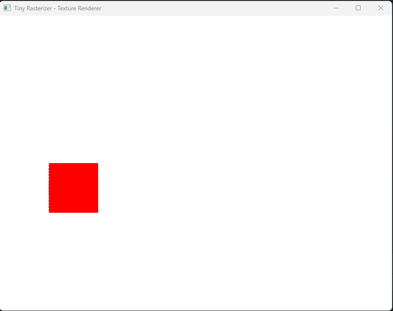
Drawing a Quad
Now, let's use our new function in main.cpp to draw a red quad. A quad can be made from two triangles. We'll define 4 vertices and 6 indices (2 triangles * 3 indices/triangle).
Here are the vertices for our quad:
- V0: (100, 300)
- V1: (200, 300)
- V2: (200, 400)
- V3: (100, 400)
And here's how we'll form two CCW triangles from them:
- Triangle 1: V0, V1, V2 (indices: 0, 1, 2)
- Triangle 2: V0, V2, V3 (indices: 0, 2, 3)
Let's update main.cpp:
#include <iostream>
#include <SDL2/SDL.h>
#include <vector> // Make sure to include vector
#include "draw.h"

// ... clear_pixels function ...

int main(int, char**) {
    // ... SDL setup ...

    while (running) {
        // ... event handling ...

        // Lock texture to write pixels
        uint32_t *pixels;
        int pitch;
        SDL_LockTexture(texture, nullptr, reinterpret_cast<void **>(&pixels), &pitch);
        pitch /= 4;

        // Clear to white
        clear_pixels(pixels, pitch, height, 0xFFFFFFFF);

        // Define vertices and indices for a quad
        std::vector<Point> vertices = {
            Point(100, 300), Point(200, 300), Point(200, 400), Point(100, 400)
        };
        std::vector<int> indices = {
            0, 1, 2,  // First triangle (v0, v1, v2)
            0, 2, 3   // Second triangle (v0, v2, v3)
        };

        // Draw the quad using our new indexed drawing function
        draw_indexed(pixels, width, height, vertices, indices, 0xFF0000FF); // Red quad

        SDL_UnlockTexture(texture);

        // Render texture
        SDL_RenderClear(renderer);
        SDL_RenderCopy(renderer, texture, NULL, NULL);
        SDL_RenderPresent(renderer);
    }

    // ... SDL cleanup ...
    return 0;
}
And here is the result! A solid red square drawn using just one API call. This approach is much more scalable and is how modern graphics APIs work.
With this new indexed drawing function, you can now easily render more complex 2D shapes by simply defining their vertices and the indices that form the triangles.
The weird edge
Something you may have noticed in our drawn objects is that there is a side that looks very sharp compared to the normal. You might think this is because there is no anti-aliasing, but actually, there is another reason.
Remember when we said a point is a pixel? That's not entirely accurate because a pixel is a small rectangle. Someone might say, "So what? What's the big deal?" Here’s the big deal: when we calculate the weights to decide whether to color this pixel or not, we are actually checking only the edge of the pixel rectangle. To solve this issue, we need to center our checking point by adding $0.5$ to the point itself.
In our $X$ loop in draw_triangle function we need to replace our point definition with that
for (int x = minX; x <= maxX; x++) {
 Point p = {
                static_cast<float>(x) + 0.5f,
                static_cast<float>(y) + 0.5f
            }; // pixel center
//Calculating weights and filling the color
}